

1519 Target Utility Setup
Windows® Hardware Installation (USB Port)
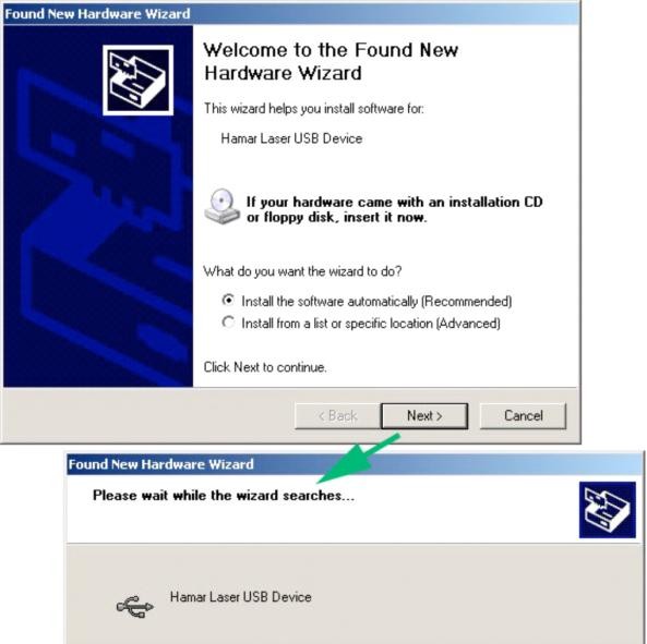
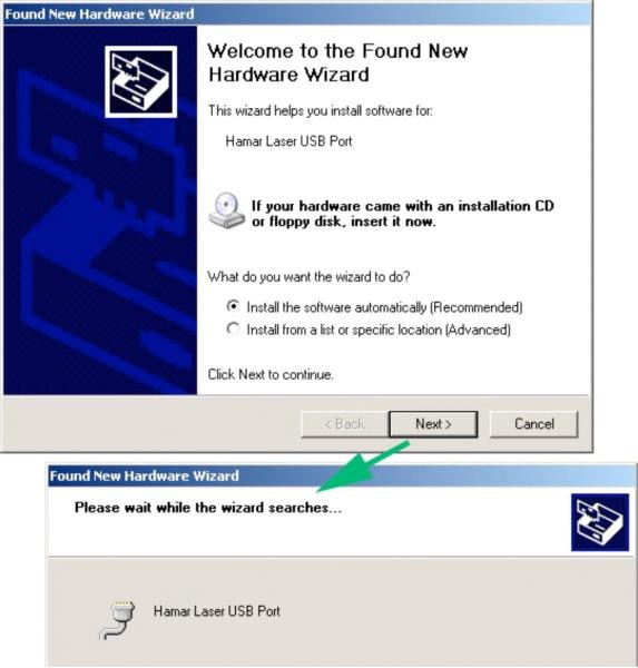
The first time that you connect a target or the Radio Transceiver to a USB port on the computer, Windows identifies the device and automatically creates a virtual COM port. Connect the USB cable to the target or Radio Transceiver and then to any available USB port on the computer. The Windows Found New Hardware Wizard (see Figure 1 and Figure 2) displays a number of times.
Each time the Wizard displays, select:
- Install software automatically
- Click Next
- Wait for the next step to complete
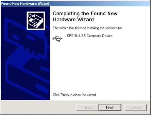
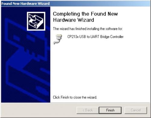
- Click Finish (see Figure 3)
Click the Setup icon to install the utility.
Installing and Using the A-1519/1520 Type II Configuration Utility
The Configuration Utility is not required for normal operation. Hamar Laser pre-configures the targets with operating parameters that are suitable for most applications. The Configuration Utility is used for the following functions:
- Firmware (Microprocessor program) Updates
- Calibration Data Table Uploading (normally done by Hamar Laser. A Calibration Station is required)
- Configuration of Internal Dampening Mode (Averaging)
- Configuration of Background Light Periodicity Sync Frequency (50Hz/60Hz AC power line frequency)
- Checking Firmware/Memory Status
- Diagnostic Readout
Installation
- Click the Setup icon to install the utility.
- Follow the screen prompts and select the defaults. If prompted to replace existing files, always keep the newest files.
- After Setup completes, click Start>Program Files>Hamar Laser Utilities. Click A-1519 Type II Configuration Utility to start the program.
Users Database
The Configuration Utility uses a Users Database to assign permission levels to multiple users. Users must log in with a user name and password to configure the target, update firmware, etc. The person designated as the Primary Administrator on the computer should perform the initial software setup. The Primary Administrator has permission to add or remove users.
Initial Setup
Start the Configuration Utility Application. If it is the first time the application is initialized and a Users Database is not present, you will be asked to log in as a temporary user with administrator privileges. This temporary account is used to create the Users Database. Once the Users Database is created, the temporary account is deactivated.
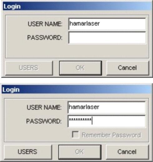
Enter the following:
User Name: hamarlaser (not case sensitive)
Password: hamarlaser (case sensitive)
After entering the correct user name and password, the Users button is enabled (see Figure 4). Click on the Users button.
Editing the User Database
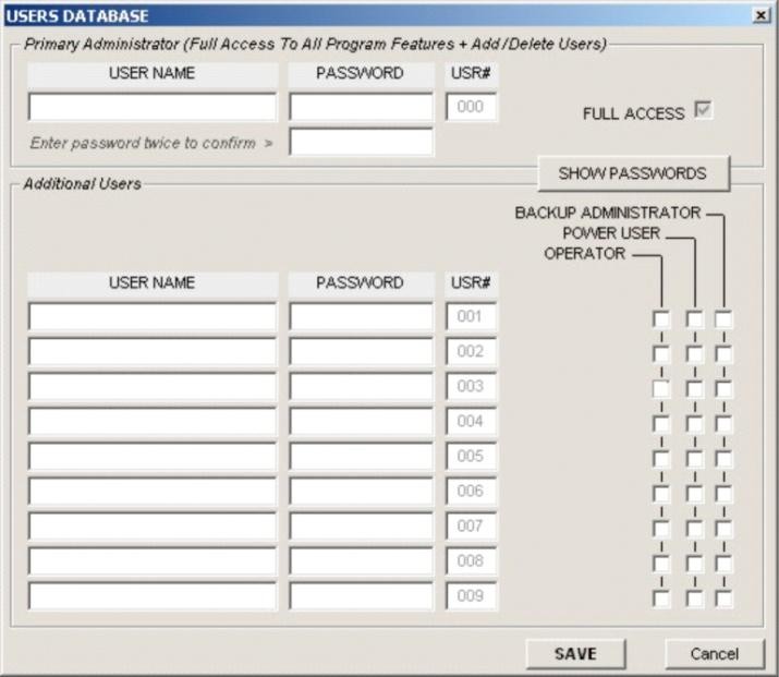
Upon initialization, the Users Database is blank and a Primary Administrator account must be created. Additional Users with three different permission levels may also be entered. Click Show Passwords to make the passwords visible on the screen as they are entered into the database (see Figure).
Permission Levels are as follows:
- Primary Administrator (single account) This user has access to all program features and has permission to add and remove users.
- Backup Administrator This user has the same access to program features as the Primary Administrator. Has permission to add and remove Additional Users only. Backup Administrators cannot make changes to the Primary Administrator account.
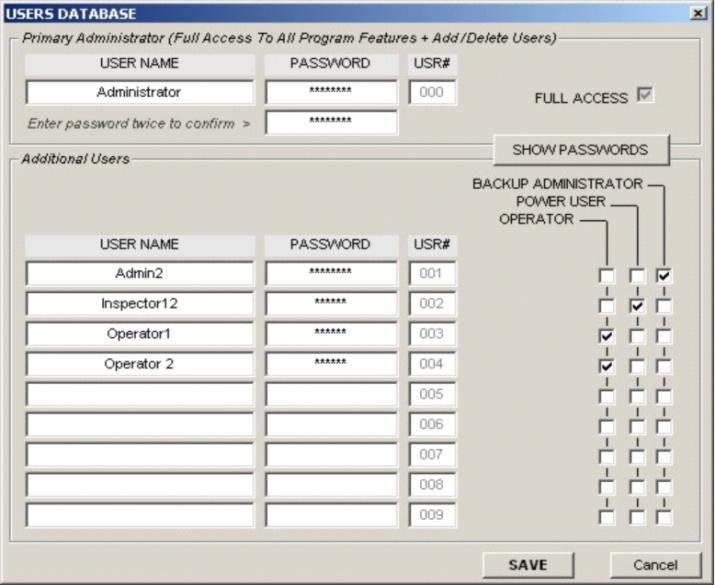
Figure 6 – Example of Users Database with 5 User Accounts - Power User
This user can access to all program features, but does not have permission to access the Users Database. - Operator
This user has access to basic configuration features, but does not have permission to Update Firmware or Calibration Data and Critical Configuration parameters. - User Not in Database
This user has access to Target Status and Diagnostic Readout only.
To edit the Users Database:
- Enter the Primary Administrator’s User Name and Password (twice)
- Enter any Additional User Accounts as needed.
- Click SAVE when you are finished adding users.
Figure provides an example of five user accounts, including one Primary Administrator, one Backup Administrator, one Power User and two operators.
Logging In

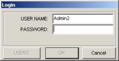
- Click the LOGIN button (the following information refers to the sample Users Database shown in Figure ).
- Enter User Name (shown in Figure as Admin2).
- Enter the password for this user.
- Click OK. The LOGIN button changes to LOGOUT (see Figure ). If you log in with Administrator privileges, always click on the LOGOUT button or close the application when you are finished using it.
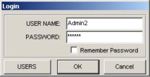
When a User Name is entered that exists in the Users Database and a valid password for that user, the OK button is enabled to indicate that the password is valid. Note that the Users button is also enabled because user Admin2 is a Backup Administrator with permission to edit the Users
Database.
To have the application remember your User Name and password for future login, check Remember Password (see Figure ). Do not check Remember Password when logging in with Administrator privileges because any user logging in afterward will have access to the Users Database.

Startup
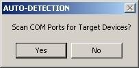
After the initial setup, you will be prompted to Scan COM Ports for Targets each time the Configuration Utility runs (see Figure ). Do not click YES until the target is connected to the computer and powered on by a scanning laser.
When a target is detected, one of the following messages displays.
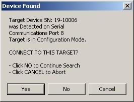
Target Connected in Configuration Mode (Figure )
The target must be in Configuration Mode to perform the following functions:
- Firmware updates
- Change configuration parameters
- Change application mode
When a target is in Configuration Mode, the status LEDs (see Error! Reference source not found., Front View) blink slowly, approximately once every three seconds.
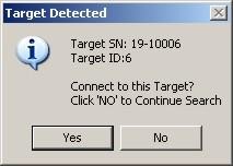
Target Connected in Application Mode (Figure )
The target must be in Application Mode to be used with standard applications that require position information in standard packet format. In addition, Diagnostic Readout is only functional in
Application Mode.
When the target is in Application Mode, the Status LEDs (see Error! Reference source not found., Front View) will be lit continuously.
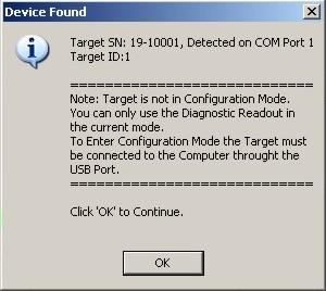
If a target is detected in Application Mode, you may also receive a message stating the Configuration Mode is not active (see Figure). Match the Serial Number shown in either message with the Serial Number on the target label. Click YES if the numbers match; click NO to search for other targets.
If the Configuration Utility fails to detect the target, the NO DEVICES FOUND message box displays (see Figure ).
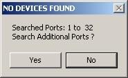
Note: Normally a target should be present in one of the first 16 ports. Occasionally, however, particularly if you are connected through a USB Hub, Windows will assign a virtual COM Port number higher than 32.
Click YES to continue searching for target(s) on higher port numbers.
Click NO if you are sure that the target is connected to a port number within the range of the port numbers shown in the message box (see Figure ).
Troubleshooting
If you are sure that the target is connected to a port number within the range of the port numbers displayed in Figure , check the following:
- Is the USB driver installed? If not, refer to the section titled Pre-installing the Common USB Port Driver (A-1519/1520 and A-910) SiLabs CP210x USB to UART Bridge Controller on Page Error! Bookmark not defined..
- Ensure that the target USB cable connectors are fully inserted into the computer and target.
- Ensure that the target is ON. The center LEDs (see Error! Reference source not found., Front View 2-
1) should be lit continuously if the target is in Application Mode or blinking once every three seconds if the target is in Configuration Mode. - Ensure that the laser is ON and scanning across the position sensor (see Error! Reference source not found., Front View 2-4).
- Click the SCAN PORTS button to rescan the ports (see Figure ).
Switching Between Normal Application Mode and Configuration Mode
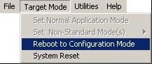
If the target is in Application Mode:
From the Target Mode Menu, select Reboot to Configuration Mode (see Figure ).
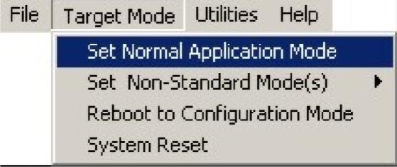
If the Target is in Configuration Mode:
From the Target Mode Menu, select Set to Normal Application Mode (see Figure ).
Note:
If you log in with Power User or Administrator privileges, you may also select Non-Standard Mode(s) shown in Error! Reference source not found.. Non-Standard Mode(s) is used for special functions, such as hardware debugging using the Diagnostic Readout. Remember to set the Target to Normal Application Mode before closing the Configuration Utility.
Click System Reset to force the target to power down and restart.
Updating the Firmware

- Log in with a Power User or Administrator access level.
- If the target is in Application Mode, select Reboot to Configuration Mode as shown in Figure .
- Wait for the utility to re-acquire the target.
- Click Firmware. You will be prompted to locate the firmware file. Firmware update file names are prefixed with A-1519/1520 and have an extension of .hfw. For example, firmware revision 8.44b would have a file name of UNI2V8.44B.hfw.
- Locate the A-1519/1520 Type II firmware update file and click OPEN.
- Wait for the utility to finish processing the file for uploading to the target (see Figure ).
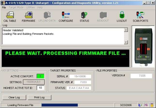
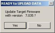
When the file processing completes, verify that you want to update the target firmware with the specified file version (see Figure ). The firmware version that is presently installed in the target is shown in the Target Properties area of Figure . In that example, the target is using firmware version 7.033. Click YES to upload the new firmware version, or click NO if the file version is lower or the same as the target version.
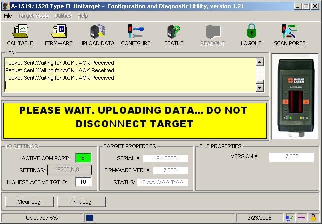
Do not disconnect the target while the firmware upload is in progress (see Figure 3).
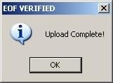
When the upload completes, an EOF (End of File) verification message displays (see Figure). Click OK.
Configuration Parameters
Note: To configure target parameters, you must be logged in as an Administrator or Power User.
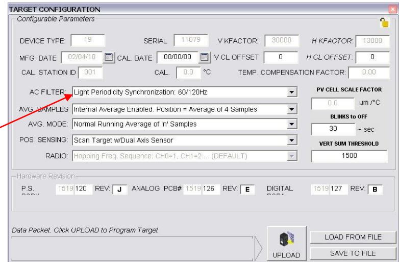
Click the CONFIGURE menu button (see Figure 2).
The Target Configuration Window displays (see Figure 4). The following fields are disabled (reserved for Hamar Laser use only):
- Device type
- Serial
- V KFactor
- H KFactor
- Mfg. Date
- Cal. Station ID
- Cal
- Temp Compensation Factor
- PV Cell Scale Factor
- All Hardware Revision
- Radio
AC Filter
Light Periodicity Synchronization
This setting is used by the incident light noise compensation filter to minimize the effects of background light intensity fluctuations on the position sensor signal. The intensity of most light sources, such as fluorescent lighting, fluctuates at the AC line frequency or twice the AC line frequency.
Set the Light Periodicity to the AC line frequency at the location where the target will be used as follows:
- 60/120Hz (United States)
- 50/100Hz or 60/120Hz (other countries)
Note: DEBUG is for Hamar Laser use only.