

Troubleshooting Guide
Troubleshooting Guide
Contents
- Troubleshooting Guide L-730/L-740 Series
- Troubleshooting Guide L-700 & L-705
- Appendix A – L-730/740 Series Laser AC Adapter Power Connector
- Appendix B – Replacing the Universal IR Receiver Battery
- Appendix C – Determining COM Port For Use In Software Setup
- Appendix D – Setting System ID & Target Network ID
- Appendix E – Using the A-910 Radio Transceiver/Hub
- Appendix F – Resetting PDA
- Appendix G – Replacing the Batteries in the L-700 & L-705 Lasers
- Replacing the Batteries L-705
Troubleshooting Guide L-730/L-740 Series
| Problem | Possible Solutions | |
|---|---|---|
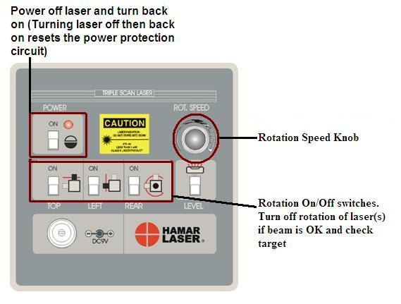
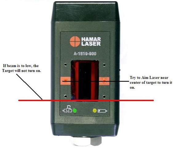
| 1 | Laser turret spinning and A-1519/1520 target not detecting laser (target LED not illuminated) |
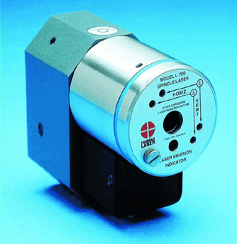
Figure 1 – Control Panel – L-743 & L-733 Lasers
|
| 2 | Turret spinning; laser beam not on |
|
| 3 | Laser beam on; turret not spinning |
|
| 4 | Laser not spinning and no
laser beam |
|
| 5 | Noisy target
(A-1519/1520) readings on PDA |
|
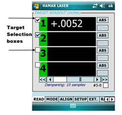
| 6 | No target readings in PDA. Target LEDs illuminated (means target is detecting laser) |
|
| 7 | No target readings in software. Target LED illuminated |
|
| 8 | Target LEDs Blink – Laser
Beam OK and Rotating |
|
| 9 | “OFF TGT” shown in target display – PDA |
|
| 10 | Cannot see level vials |
|
| 11 | “Runtime Error” in software |
|
| 12 | Software crashes upon loading |
|
| 13 | PDA locks up |
|
| 14 | PDA turns off automatically |
|
| 15 | PDA is frozen |
|
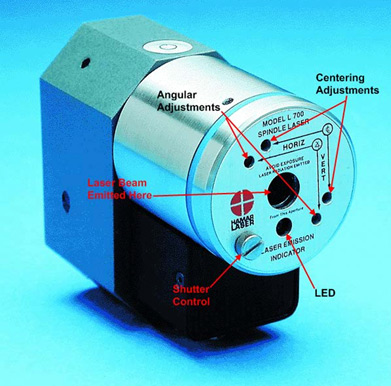
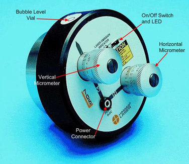
Troubleshooting Guide L-700 & L-705
| Problem | Possible Solutions | |
|---|---|---|
| 1. | No Laser Beam
|
|
| 2. | Beam Is Not Round (use white paper to see beam) |
|
| 3. | Beam has satellites (use white paper to see beam) |
|
| 4. | “—” shown in Software Target Display |
|
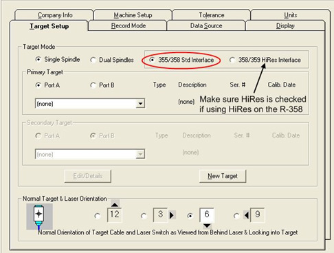
| 5. | If green LED on R-358 is illuminated, but there are “—-” in the display |
|
| 6. | “OFF TGT” Shown in Target Display |
|
| 7. | Numbers in Target Display Jump Wildly |
|
| 8. | Numbers in Target Display are noisy(jump up/down by more than 0.002 mm in
2 meters) |
|
| 9. | Software Crashes upon Loading |
|
| 10. | No Negative (or Positive) readings are displayed |
|
| 11. | Get very odd results |
|
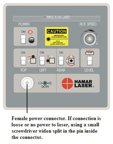
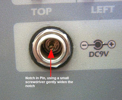
Appendix A – L-730/740 Series Laser AC Adapter Power Connector
Appendix B – Replacing the Universal IR Receiver Battery
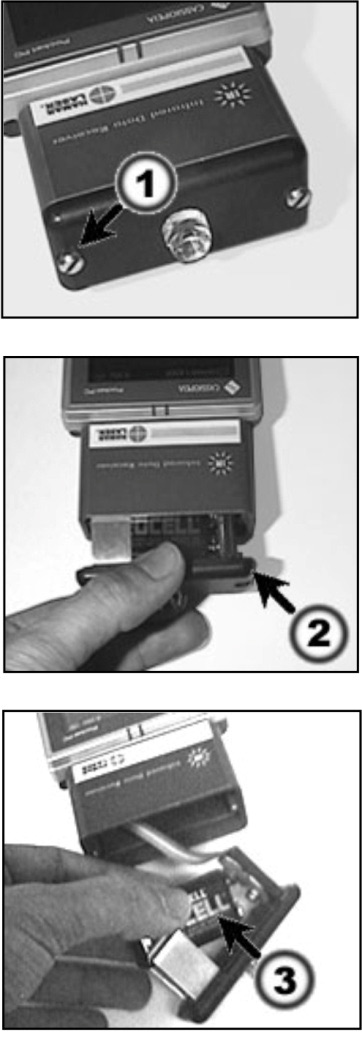 The following provides instructions for replacing the IR receiver battery, with illustrations showing the PDA version of the IR receiver. The same battery replacement procedure applies to the PC version.
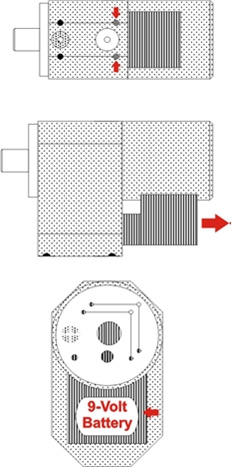
A single 9-volt battery powers the Universal IR receiver. The battery is located inside the receiver head assembly (2).
To replace the battery:
- Remove the two screws (1) securing the receiver assembly (2).
- Slide the assembly out until the battery is fully exposed. Do not overstretch the signal cable.
- Replace the battery (3).
- Carefully slide the receiver assembly (2) back into place, allowing the cable to fold back into the original position over the battery.
- Secure the receiver assembly with the thumbscrews (1). Do not over tighten.
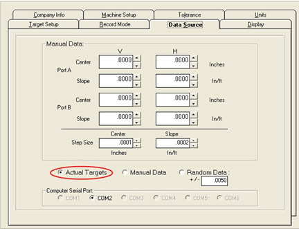
Appendix C – Determining COM Port For Use In Software Setup
- Click on Start, Settings then Control Panel.
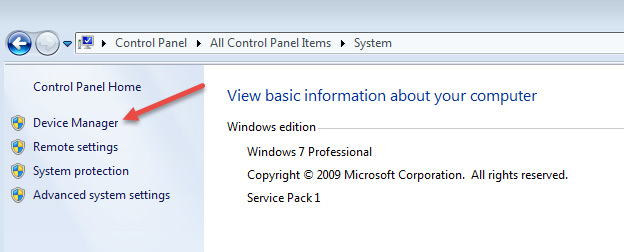
- In Control Panel window, double click on “System icon.
- At the top left of the next window click on “Device Manager”
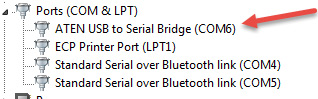
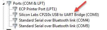
- In Device Manager, click the ” ” sign next to “Ports (COM & LPT). It will display “ATEN USB to Serial Bridge (COM#) if you are using the USB to Serial Adapter cable (with the R-358 or R-355) or Silicon Labs CP210x USB to UART Bridge (COM#) if you are using an A-910 transceiver (# being the COM port being used) Make sure that you have the correct COM port checked in your software.
Appendix D – Setting System ID & Target Network ID
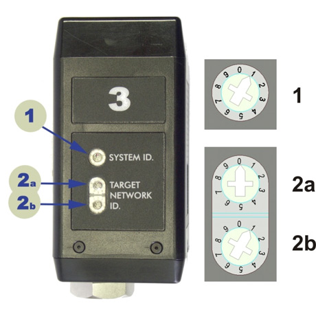
Setting the System ID
Note: Before selecting a System ID, ensure that it is not already in use by another system within the radio coverage area.
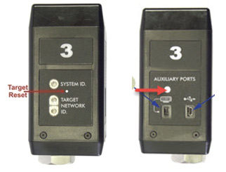
Using a small screwdriver, rotate Switch 1 to align the arrowhead with the System ID number (0-9). Figure 6 shows the System ID switch set to 1.
Setting the Target Network ID
- Locate DIP Switches 2a and 2b on the target (see Figure 6).
- Figure 6 – Configuration (DIP) Switches
- Set the ID as follows:
- For Target Network ID 01 to 09: Use a small screwdriver to rotate switch 2a so that the arrowhead points to 0. Rotate switch 2b (lowest switch) to 1-9, accordingly.
- For Target Network ID 10 to 99: Use a small screwdriver to rotate switch 2A so that the arrowhead points to the first digit of the ID number, and then rotate switch 2b to the second digit of the ID number.
For example: To set Target Network ID=25, set switch 2A to “2” and switch 2b to “5”.
Notes:
- Do not set more than one target to the same Target Network ID and the same System ID. In addition, there cannot be more than one Radio Transceiver with the same System ID within radio range.
- The label with the large number ‘3’, shown in Figure 6, is optional. By default, Hamar Laser ships each target pre-configured with a Target Network ID set from 01 to 09 and with a label that matches the Target Network ID. Additional Labels can be purchased in sheets, with consecutive label pairs (one for each side) numbered from 0 to 9 or 10 to 19. Higher numbered labels may not be stocked but are available upon request.
Appendix E – Using the A-910 Radio Transceiver/Hub
Front Panel Features
- Power ON indicator and Low Battery indicator
- Internal backup battery charging indicator and USB LINK ESTABLISHED indicator
- TX indicator: Blinks when device is transmitting data to the target(s)
RX indicator: Blinks when the device is receiving data from targets or other transceivers - Not used
- System ID setting switch
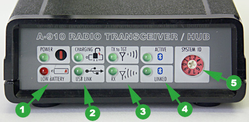
Figure 7 – The A-910 Radio Transceiver/Hub FRONT PANEL
Rear Panel Features
- Not used
- USB/Data I/O Port
- Power Switch
- External power supply: required only for computers that cannot provide adequate power (5V, 400 mA) through the USB port
- Antenna
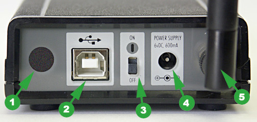
Figure 8 — The A-910 Radio Transceiver/Hub REAR PANEL
Appendix F – Resetting PDA
Dell & HP PDA
Soft Reset
NOTE – When you do a soft reset, the device deletes any data or active programs that have not been saved in the flash memory. Try a soft reset if the PDA does not respond when tapping the screen or pressing any of the buttons.
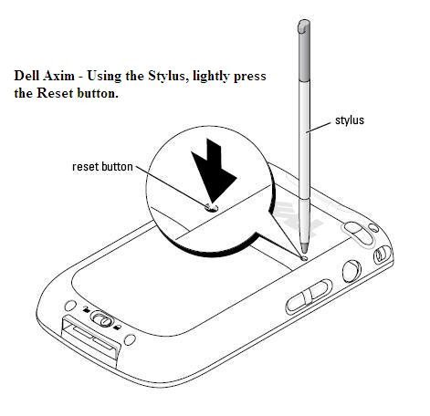
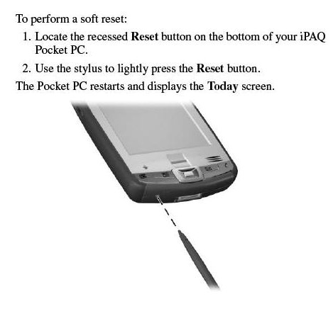
The left diagram shows how to reset a Dell Axim PDA. The diagram on the right shows how to reset a HP IPAQ.
Nomad PDA
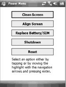 Power menu: Hold down the Power key for about 3 seconds to display a countdown. Continuing to press the Power key will cause a reset when the countdown reaches zero. If you release the Power key while the countdown is proceeding, you access the following menu. Tap an option or OK to exit.
Clean Screen: Disables the touchscreen for cleaning. Press the enter key to re- enable the touchscreen.
Align Screen: Repeats the alignment procedure.
Replace Battery/SIM: Ensures that alarms will not wake up the unit while changing the battery or the SIM on WWAN units.
Shutdown: Intended for long term storage to put the unit in its lowest power mode. Running application state, unsaved data, and real-time clock settings will be lost. Internal GPS parameters will be reset to their default settings. To take the unit out of the shutdown mode, press the power key and the unit will boot up.
NOTE: While in shutdown mode, the battery LED does not work, but if the power supply is plugged in, it will still charge.
Reset: Stops all running programs and restarts the unit. No file system data is lost, only open or unsaved files will be lost. All registry settings, control panel, personal information, GPS settings and databases are preserved.
NOTE: if the countdown or the Power menu does not appear when the power button is held down, continue to hold down the power button for at least 20 seconds to reset it.
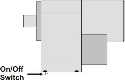
Appendix G – Replacing the Batteries in the L-700 & L-705 Lasers
 The L-700 Lasers use a standard, replaceable 9-volt battery for up to 8 hours of continuous use. For best results, use alkaline or rechargeable Nickel-Cadmium (NiCad) batteries.
To install or replace the battery:
- Remove the battery cover.
Using the 3/32″ hex key included with the laser, loosen the two
hex screws on either side of the bubble level. The screws do not need to be removed. - Slide the cover out.
Pull the cover straight out of the laser to access the battery. - Replace the battery.
Remove the battery (rock it gently from side to side to disconnect it) and replace it with a new 9-Volt battery. Make sure the battery is seated in the clips. If the battery won’t snap in, check to see if the clips are bent or distorted. - Slide the cover on and tighten the screws.
Replacing the Batteries L-705
The battery pack uses two 9-volt batteries. The batteries are housed in a two-part case which is held together by flathead screws. Hamar Laser recommends using alkaline or nickel-cadmium (NiCad) cells for best performance.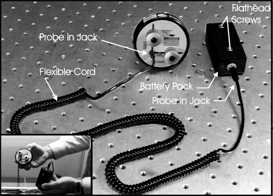
- Unplug the battery pack from the laser.
Pull the probe out of the laser control panel and gently set aside. - Unscrew the cover of the pack.
Locate and loosen the two captive flathead screws, and remove the cover. - Replace the two batteries.
Remove the old batteries and replace them with new 9-volt cells, being careful to orient them with the negative terminal out (or up). - Re-attach the cover.
Put the cover back on and secure it to the battery pack with the screws.