

How to Calibrate the Level Vials
Calibrating the Level Vials
Note 1: This procedure calibrates only one level vial at a time and must be repeated for the other axis.
Note 2: It is very important to warm up the laser for at least 30 minutes before starting this procedure. It is also very important to level both the Pitch and Roll axis level vials during this procedure. Failure to do this makes it nearly impossible to calibrate the levels.
The calibration procedure involves a series of steps to adjust the laser beam to be level to earth. Because the leveling process is subject to so many variables, repeat the procedure to check for accuracy once the initial readings are taken and adjustments are made. A typical sequence would be as follows:
- Determine the set point and set the first axis.
- Use the set point value to set the second axis.
- Check both the first and second axes. Reset the levels if necessary.
- If the levels are reset, make a final check to determine if the laser level error is acceptable.
When calibrating the precision level vials, work on a surface that is level to earth within .001 to .002 inches per foot. A surface that is 10 to 20 feet in length is ideal. When calibrating to shorter surfaces, do so with the readout set to the .0001″ mode. If you are using the A-1519 or A-1520 Wireless Targets with the R-1355 PDA or with Hamar Laser’s alignment programs, set the readout display through the software.
Zeroing the Targets
The following sections refer frequently to “zeroing” the target. When a target is zeroed, the readout is reset to zero at the point where the laser beam currently hits the target cell.
When using the A-1519/A-1520 Universal Targets, this is accomplished through the Read9 software (or through Hamar Laser’s other alignment programs) . This reading is stored in memory and then subtracted from all future readings. Once the target is zeroed, subsequent readings show only the difference from the original reading.
Calculating the Calibration of the Level Vials – Roll Axis
Note: It is very important to warm up the laser for at least 30 minutes before starting this procedure. It is also very important to level both the Pitch and Roll axis level vials during this procedure. Failure to do this makes it nearly impossible to calibrate the levels.
- Level the laser.
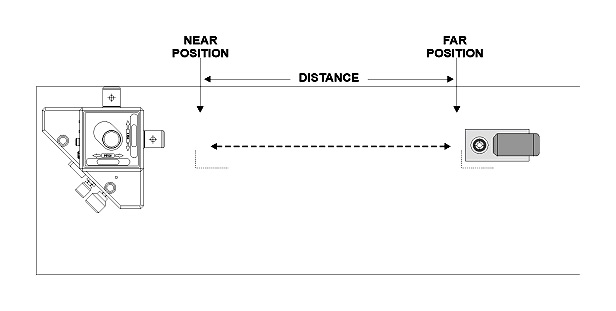
Using the adjustment knobs, level the laser so both the pitch and roll levels are exactly level (see top of Figure 4). - Zero the target in the Near Position.
Beginning with the Roll Axis, place a target on a point near to the laser. Mark this point so you can always reposition the target at the same point. Zero the target according to the readout you are using. - Determine Far Reading 1.
Move the target to the Far Point, mark this point and record the target reading. This is Far Reading 1. Measure the distance (D1) between the Near Point and the Far Points and write it down.
Note: It is recommended to repeat the measurements two or three times to check repeatability. - Determine Far Reading 2.
Rotate the entire laser unit 180 degrees. Re-level the laser using the adjustment knobs so both the pitch and roll levels are exactly level. Return the target to the Near Position, ensuring that it is placed in the exact position as before. Re-zero the target on this point. Move the target back to the Far Position, again ensuring that it is positioned exactly as before. Record the target reading. This is Far Reading 2.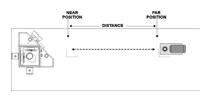
Figure 3 — Setup after rotating the laser 180 degrees - Calculate the Set Point – Roll Axis
Add Reading 1 and Reading 2 and divide by 2 (Set Point). Divide the Set Point by the D1 (distance between the points). The result is the calibration of the level vial in units of inches/ft. or mm/M. To be within specifications, the calibration result should be as follows:Split Prism Vial Assembly: ≤ .00006″/ft. (0.005 mm/M)
Standard Levels: ≤ .00012″ /ft. (0.01 mm/M)Example:
15 feet (D1)
.000 (Near Reading).020 (Far Reading 1)
+ -.010 (Far Reading 2)
_____________________________________
+.010 (Sum of the two readings)+.010 / 2 = +.005 (Set Point)Calibration = Set Point / D1
.005 / 15 = .0003 inches/ft. (out of spec)If this value is out of the specification, then you will need to use the Set Point to bring it back into specification. See the first step in the next section.
Setting the First Level Vial – Roll Axis
- Tilt the laser to the Set Point
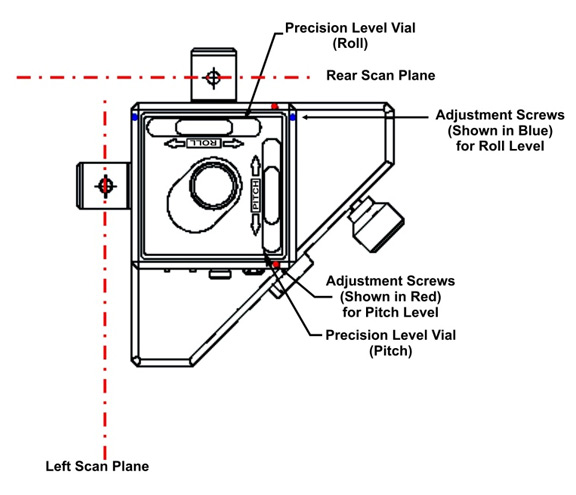
Figure 4 – L-733 (top view) showing location of Precision Level Vials and corresponding adjustment screws Move the target back to the Near Point to verify it still reads zero. If not, re- zero it. Then move the target back to thFar Point and tilt the laser by adjustinthRolAxiadjustment knob on the laser base until the readout displays the calculated Set Point.
- Adjust the level.
Locate the two recessed adjustment screws for the Roll Axis level you are adjusting (see Figure 8). Using thwrench provided, adjust the level assembly until the bubble is centered in the window for the Standard Level Vials or the two halves of the bubbles line up for the Split
Prism Level Vial (see Figure 4 and Figure 5). For example, to move the bubble to the left, loosen the left screw and tighten the right screw. When the bubble is centered, tighten the left screw until the bubble is stationary. Check your work by repeating these steps and ensuring that the level is calibrated to within the specified tolerances.
Note: Tighten the set screws just firmly enough to hold the window assembly in place. Over- tightening these screws may cause damage.
Calculating the Calibration of the Levels Vials – Pitch Axis
-
- Level the laser.
Rotate the entire laser unit 90 degrees to calibrate the Pitch Axis level vial. Using the adjustment
knobs, level the laser so that both the pitch and roll levels are exactly level. - Zero the target in the Near Position.
Set the target on the same Near Position as before and re-zero it. - Determine Far Reading 1.
Move the target to the same Far Position as before and repeat Step 3 (Roll Axis) above. - Determine Far Reading 2.
Rotate the entire laser unit 180°. Re-level the laser using the adjustment knobs so both the pitch and roll levels are exactly level. Return the target to the Near Position, ensuring that it is placed in the exact position as before. Re-zero the target on this point. Move the target back to the Far Position, again ensuring that it is positioned exactly as before. Record the target reading. This is Far Reading 2. - Calculate Level Calibration and the Set Point – Pitch Axis
Add Reading 1 and Reading 2 and divide by 2 (Set Point). Divide this Set Point by the D1 (distance between points). The result is the calibration of the level vial in units of inches/ft. or mm/M. To be in specification, the calibration result should be as follows:Split Prism Vial Assembly: ≤ .00006″/ft. (0.005 mm/M)
Standard Levels: ≤ .00012″ /ft. (0.01 mm/M)Example:
15 feet (D1)
.000 (Near Reading).035 (Far Reading 1)
+ .010 (Far Reading 2)
_____________________________________
.045 (Sum of the two readings)
+.045 / 2 = +.0225 (Set Point)Calibration = Set Point / D1
.0225 / 15 = .0015 inches/ft. (out of spec)If this value is out of the specification, then you will need to use the Set Point to bring it back into specification. See Step 6 below.
Setting the First Level Vial – Pitch Axis
- Tilt the laser to the Set Point
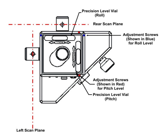
Figure 5 – L-733 (top view) showing location of Precision Level Vials and orresponding adjustment screws Move the target back to the Near Point to verify it still reads zero. If not, re-zero it. Then move the target back to the Far Point and tilt the laser by adjusting the Pitch Axis adjustment knob on the laser base until the readout displays the calculated Set Point.
- Adjust the level.
Locate the two recessed adjustment screws for the Pitch Axis level yoFi are adjusting). Using the wrencc provided, adjust the level assembly until the bubble is centered in the window for the Standard Level vials or the two halves of the bubbles line up for the Split Prism Level vial (see FiguranFigur5). For example, to move the bubble to the left, loosen the left screw and tighten the right screw. When the bubble is centered, tighten the left screw until the bubble is stationary. Check your work by repeating these steps and ensuring that the level is calibrated to within the specified tolerances.
Note: Tighten the set screws just firmly enough to hold the window assembly in place. Over- tightening these screws may cause damage.
- Level the laser.
Checking the Levels for Accuracy
To check for accuracy, repeat the steps for setting the precision level vials. The Set Point should be the same as the previous Set Point. If not, calculate a new set point and adjust as necessary.