

How to use the NORMIN Method to Qualify a Laser
The NORMIN Method (Bore and Spindle)
The NORMIN method was developed by Hamar Laser Instruments as a way of compensating for laser or target mounting errors in bore or spindle work. The word is a contraction of “NORMal-INverted,” which briefly describes the method. It is quite similar to the four clock readings taken with dial indicators, but uses a laser and a target instead. The NORMIN method is used in conjunction with simple fixtures and targets that allow inexpensive, precision measurement. The target/fixture is set in the bore or spindle in the NORMal position (cable down) and the readings are recorded. Then the target/fixture is rotated 180 degrees to the INverted (cable up) position, and a second set of readings is obtained. The two sets of readings cancel out centering errors and provide a very accurate result.
There are three centers involved in bore alignments: the True Bore Center, the Target Center, and the Laser Beam Center. If mounting fixtures were perfect, the Target Center would be located at the True Bore Center, and if perfectly aligned, the True Bore Center would be located at the laser beam center. In reality, however, they seldom line up. An example of the three centers with respect to one another is shown in Figure 1.
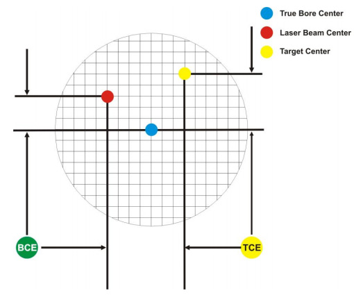
Figure 1 – Three centers of bore alignment
Two relationships can be calculated from these three centers and two sets of NORMIN readings: the Target Center Error (TCE) and the Bore Center Error (BCE). The Bore Center Error (BCE) is used when it is desirable to know the true bore centerline position relative to the laser beam center without fixture errors. Usually, the laser beam center is where a bore center should be located, and the BCE shows its actual location. The Target Center Error (TCE) is used if the operator wants to place the laser beam center exactly in the middle of a bore.
The general rule is: buck in to the TCE and measure the BCE.
The readout always shows the displacement between the Target Center and the Laser Beam Center. When the Target Center is not on the True Bore Center, the numbers and the signs on the readout will change when the target is rotated because the Target Center is moved to a different location in relationship to the laser beam.
Figure 2 represents the target in the NORMal position, with the cable down. If each square represents .001″, the Target Center is .001” higher than the Laser Beam Center (+.001″) and is .007″ to the right of the Laser Beam Center (+.007″).
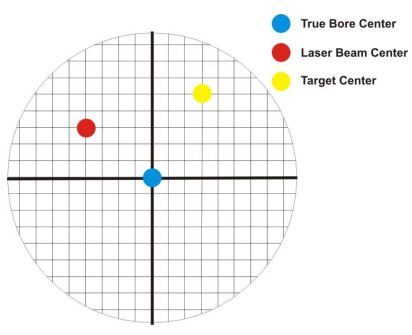
Figure 2 – Target in the NORMal position
Figure 3 represents the target in the INverted position, with the cable up. When the target is rotated, the signs on the readout are also rotated. Therefore, although the Target Center appears to be to the right of and lower than the Laser Beam Center in Figure 3, the vertical readings will be positive and the horizontal readings will be negative. When the vertical TCE is calculated, (NORMal+INverted divided by 2) the Target Center is .004″ higher and .003″ to the right of the True Bore Center in the NORMal position. The table below shows the calculation of the vertical and horizontal TCE values.

Figure 3 – Target in the INverted position
| NORMal Vertical Reading | +.001″ | NORMal Horizontal Reading | +.007″ | |
| INverted Vertical Reading | +.007″ | INverted Horizontal Reading | -.001″ | |
| Total | +.008″ | Total | +.006″ | |
| Divide by 2 = Vertical TCE | +.004″ | Divide by 2 = Horizontal TCE | +.003″ |
If you place the Laser Beam Center exactly on the True Bore Center with the target in the NORMal position, the readings will show Vertical +.004″ and Horizontal +.003″.
Appendix B – Qualifying the Laser
Lasers must be qualified; that is, the beam must be centered and made parallel to the axis of rotation. This can be either the axis of the laser’s mounting stud or of a spindle in which the laser is mounted.
All Hamar lasers are factory qualified to the mounting stud axis. Sometimes, due to slight mounting errors, it is desirable to adjust a laser so that it is aligned to the spindle’s axis of rotation rather than to its own. A laser that has been qualified for a particular application may need to be re-adjusted for another, or back to its own axis. The following procedure is used to qualify the L-700 laser to a desired axis.
This procedure is for adjusting the laser only. While the software allows the user to adjust the target, targets are factory-qualified and need no field adjustments. Attempting to do so could potentially damage the target
The NORMIN Procedure
The NORMIN method is a way of canceling mounting errors. The word is a contraction of “NORMalINverted,” which briefly describes the method.
To take NORMIN readings, the laser and target fixtures are set in the NORMal position (cable down) and the readings recorded. Then the target fixture is rotated 180 degrees to the INverted (cable up) position and a second set of readings obtained. The two sets of readings cancel out both laser and target center and angular mounting errors and provide a very accurate result.
For a detailed description of the NORMIN method, see Appendix A – The NORMIN Procedure, beginning on Page Error! Bookmark not defined..
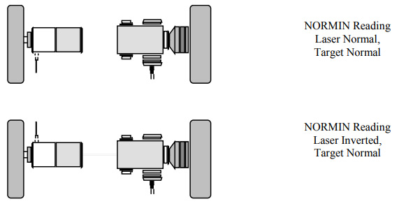
Figure 4 – Taking NORMIN Readings
Adjustments
The L-700 laser has centering and angular adjustments on the faceplate. The beam is emitted from the large hole in the center. The illustration below shows the location of the various adjustment screws.
Avoid direct exposure to the laser beam while adjusting the laser. Do not stare into the beam.

Figure 5 – Laser Adjustment Screws
Manual/Software-Assisted Qualification
To qualify a laser, error correction readings are taken to cancel out mounting and other errors and a set point is calculated. The laser beam is then adjusted to the set point, making it parallel to/coincident with the desired axis of rotation.
Manual qualifying requires the user to calculate the set point from the error correction readings before adjusting the laser to that point. A computer program, such as READ8, calculates the set point for the user, and zeroes the display at that point. The user then adjusts the laser beam to zero. While many users find the software-assisted method slightly easier, both procedures are essentially the same, and both will result in a qualified laser.
Hardware Requirements
The common equipment required to perform a qualifying procedure would be a target, an L-700 laser, and the spindle or fixture to hold the laser and target. To measure both the angle and center, a two-axis target with an angle module (the T-212) or a four-axis simultaneous target (such as the T-261) is required. If the laser is being qualified to its own mounting stud axis of rotation, the recommended fixture is the Hamar Laser Model A-801 alignment/calibration fixture.
Each method also has its own additional requirements. The manual procedure requires a readout. The software-assisted procedure requires a computer and interface and Read8 software.
Manual Qualifying Procedure
The following procedure explains how to qualify the laser with a four-axis target and a handheld readout. The best way to do this is to calculate set points for angle, and adjust the laser angle first. The user then goes back and calculates the center set points and adjusts the laser centering.
Setup
- Connect the target to the readout.
Plug the target into the readout and switch on the readout. - Set the laser and target in the spindle or fixture.
If qualifying to a spindle (or spindle mounting fixture), mount the laser in the spindle and the target in the master part. (If the beam does not strike the target cell while mounted in the spindle, move the spindle head until the readout window displays a reading and the “On-Target” light is on.)If qualifying the laser to its own mounting stud axis, mount the laser and target facing each other in the A-801 calibration fixture.
Adjusting the Laser Angle
- INvert the laser with the target in the NORMal position.
Set the laser in the Inverted (cable up) position, with the target in the NORMal (cable down) position, and wait for the readings to stabilize (approx. 10 seconds). Write down the angular INverted reading. - Rotate the laser to the NORMal position.
Rotate the laser to the NORMal (cable down) position, with the target still in the NORMal position, and wait for the readings to stabilize (approx. 10 seconds). Write down the angular NORMal reading. - Calculate set points for each axis.
Calculate the set points for each axis–vertical and horizontal angle–with the following formula:(NORMal reading + INverted reading) / 2 = Set PointIf, for example, the following vertical NORMIN readings are taken:
NORMal = .0021, INverted = -.0017, the equation would read:[(.0021) + (-.0017)] / 2 = (.0004) / 2 = .0002In this case, .0002 would be the vertical angular set point. Use the two vertical angular readings to calculate the set point for vertical angle. The horizontal angle set points would be calculated in the same way. - Adjust vertical and horizontal angle to set points.
Adjust the angle using the angular controls on the laser’s faceplate until the readout displays the calculated set points.
Adjusting the Laser Centering
- INvert the laser with the target in the NORMal position.
Set the laser in the Inverted (cable up) position, with the target in the NORMal (cable down) position, and wait for the readings to stabilize (approx. 10 seconds). Write down the center INverted reading. - Rotate the laser to the NORMal position.
Rotate the laser to the NORMal (cable down) position, with the target still in the NORMal position, and wait for the readings to stabilize (approx. 10 seconds). Write down the center NORMal reading. - Calculate set points for each axis.
Calculate the set points for each axis–vertical and horizontal center–with the following formula:(NORMal reading + INverted reading) / 2 = Set PointIf, for example, the following horizontal NORMIN readings are taken:NORMal = -.0014, INverted = -.0006, the equation would read:
[(-.0014) + (-.0006)] / 2 = (-.0020) / 2 = -.0010Thus, in this case, -.0010 would be the horizontal center set point. Use the vertical center readings to calculate the set point for vertical centering. The horizontal center set points would be calculated in the same way. - Adjust vertical and horizontal center to set points.
Adjust the center using the centering controls on the laser’s faceplate until the readout displays the calculated set points.
Checking Results
To confirm the results, invert the laser. The display should show the same reading, same sign (+ or -) as it did in the normal position, to within .0002″ in the calibration fixture (results may be slightly less accurate in a spindle due to bearing runout). If the results are not close enough, the set points may be recalculated and the laser unit readjusted.
The user should get as close to a zero difference on the readout as possible; however, in some fixtures or applications this may not be practical. If there is any doubt about consistency of results, check the repeatability of the fixture using the REPEAT function of the Read8 software. This will establish a tolerance within which the user can work.