

Target Calibration
Before a new target can be used, it should be calibrated. If the target is purchased as part of a system, it will be calibrated at the factory and the resulting calibration factors will be included with the system’s software.
If the user wants or needs to calibrate a target, the process involves moving or tilting a target a known amount from center or zero and observing the actual readings. The calibration factors are then calculated and used by the software to adjust the actual target reading to match the actual target displacement.
Four calibration factors (+V, -V, +H, -H) must be set for each two-axis target. A four-axis target (T-261, T-266, T-267 and T-212) requires eight factors (+V, -V, +H, -H, for center and for slope). Calibration factors may be entered manually, or the program may perform the calibration automatically.
Calibration Setup
- Mount the laser and target.
Note: Figure 1 shows the target mounted in the Hamar Laser A-807 fixture stand. In order to take advantage of the automated calibration features available with the Read8 software, this fixture stand must be used for calibrating center and slope targets. Mount the laser in the non-adjustable hole on the fixture. Mount the target in the tilt plate with both the target and laser in the normal position (cord down).
An appropriate target stand with micrometer stage, such as the Hamar Laser T-230, or any calibrated x-y slide may be used when calibrating center-only targets (see Figure 2).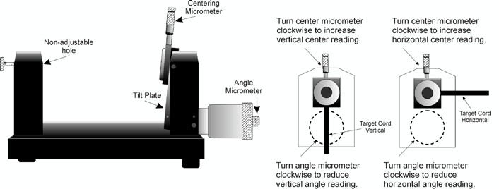
Figure 1 – Model A-807 Calibration Mounting Fixture 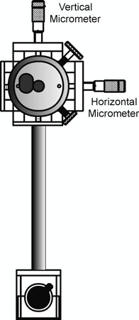
Figure 2 – T-230 Target Stand - Check all connections.
Connect the target to the interface, making note of the port to which it is connected, and ensure the interface is connected to the computer. Turn on the laser’s power supply - Start the Read8 program and select Target Setup from Setup.
Click New Target. The New Target screen displays. Click the down arrow (↓) next to the Type list box to see a list of targets (see Figure 3). Select the target you want to add. You may enter a new name for the target and the target serial number
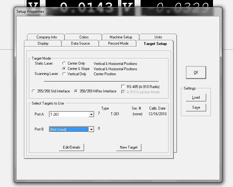
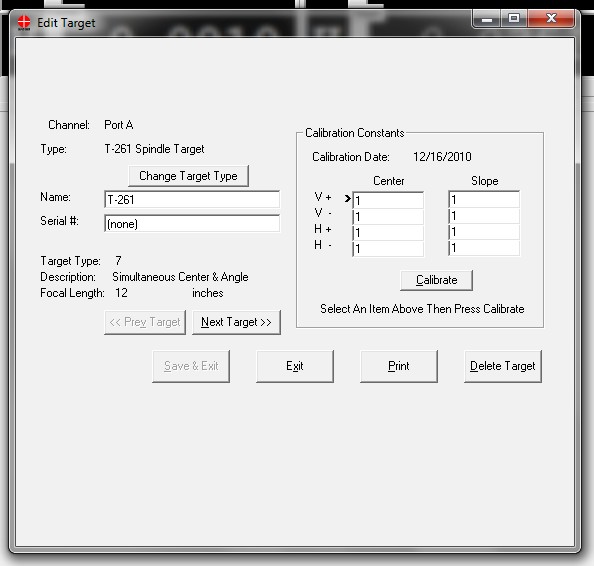
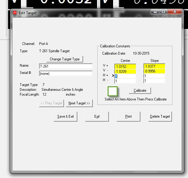
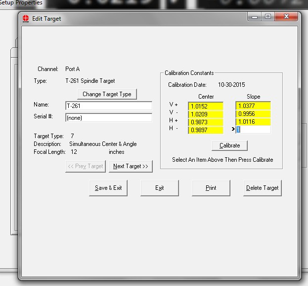
Figure 3 – New Target Screen - Select the calibration factor from the list in the Calibration Constants menu, (+V, -V, +H, -H) then click Calibrate or Press Alt-C.
Note: The preferred procedure is to calibrate the vertical axes, both center and slope if appropriate, then rotate the target in the fixture 90 degrees and calibrate the horizontal axes (see Figure 1).
If working with a fixture that has a horizontal micrometer, there is no need to rotate the target (seeFigure 2).
The Select Channel/Port for Target menu displays (Figure 4). Select the channel or the port to which the target is attached and click OK. The Calibration Screen displays and indicates the Port or Channel selected (see right arrow in Figure 5).
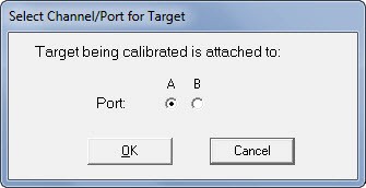
Figure 4 – Channel/Port Selection Screen
Calibrating a Center-and-Slope Target
In order to use the automated features of the Read8 software, calibration for a center-and-slope target must be performed with the target mounted in the A-807 calibration mounting fixture (see Figure 1). This fixture is equipped with both a centering micrometer and an angle micrometer.
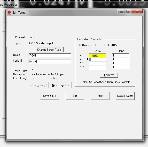
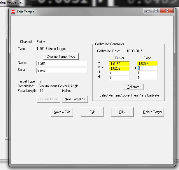
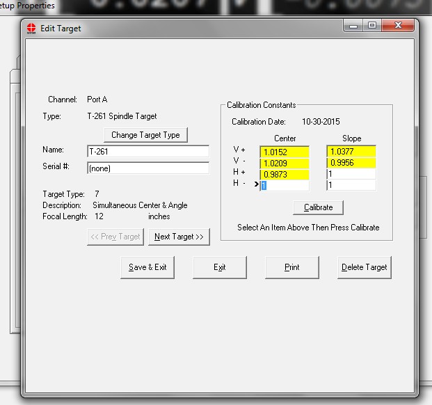
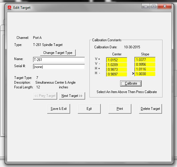
The Calibration Constants menu for center-and-slope targets requires that four calibration factors for center and four calibration factors for slope be entered (compare Figure 3 with Figure 6). The procedure is the same as that for calibrating a center-only target, however the calibration factors for slope are obtained by using the angle micrometer.
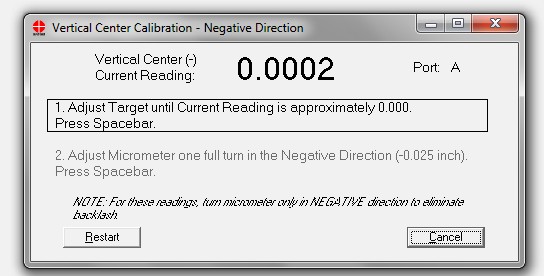
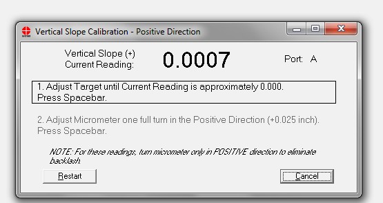
- For the first reading, (in this case V+), center the target using the centering micrometer. This corresponds to Step 1 on the Calibration Screen (see Figure 5).
- Press the spacebar to record the reading
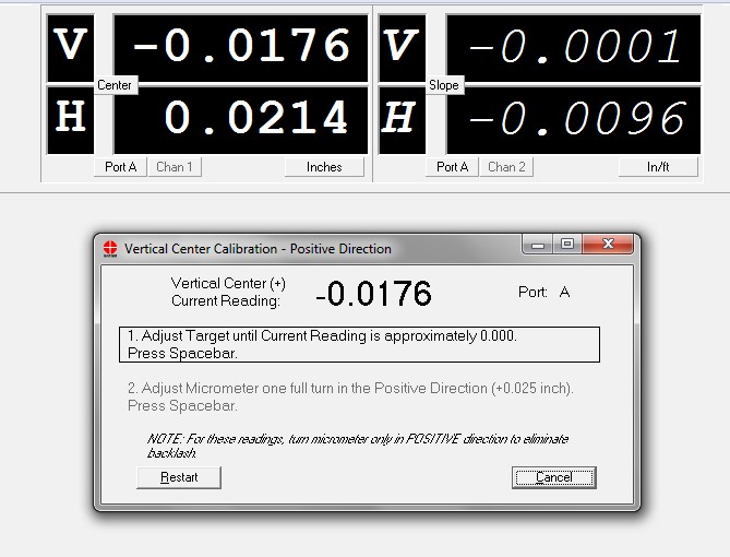
- The Vertical & Horizontal slope readings should be less than .010”/Ft. Using the small micrometer, adjust the vertical center to near zero so the micrometer ends on a line and press the space bar to record the reading.
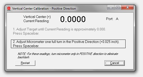
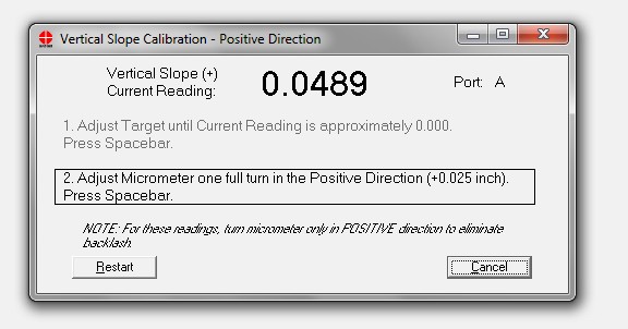
As shown, turn the micrometer 1 full turn in the positive direction.
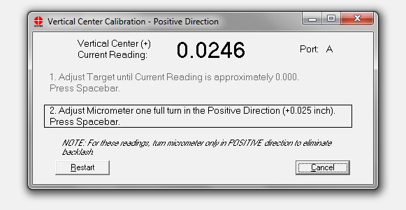
- Press the space bar to record the reading.
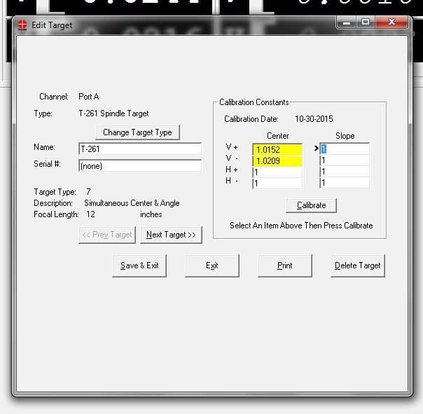
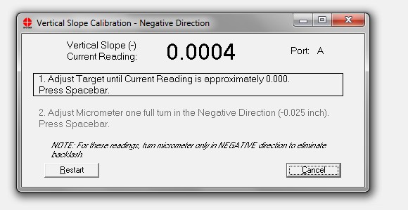
- Turn the micrometer back 1 full turn. Select V- and click calibrate.
- Press the space bar to record the reading.
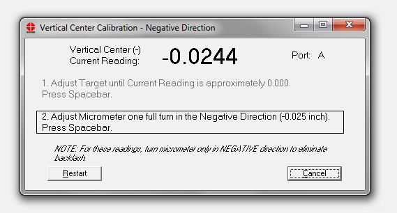
- Turn the micrometer 1 full turn in the negative direction. Press the space bar to record the reading.
- Turn the micrometer back to the starting point and select V+ Slope. Click Calibrate.
- Adjust the large Slope micrometer until the reading is near zero. Press the space bar to record the reading.
- Turn the micrometer 1 full turn in the positive direction. The reading should be near .050”. The target pivots on a 6” length so a .025” turn of the micrometer will be a .050”/Ft change. Press the space bar to record the reading
- Turn the micrometer back to the starting point and click V-Slope. Click Calibrate
- Press the space bar to record the reading.
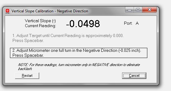
- Turn the micrometer 1 full turn in the negative direction. The reading should be near .050. The target pivots on a 6” length so 1 full turn of the micrometer (.025”) will be .050”/Ft. Press the space bar to record the reading. Turn the micrometer back to the starting point.
- Loosen the set screw that is holding the target in the A-801 fixture and turn the target 90 Degrees. The cable should be at 3 o’clock or 9 o’clock.
- Select H+ Center and click calibrate.
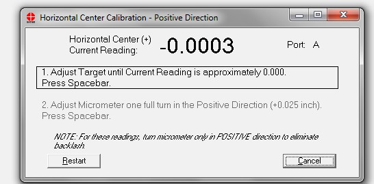
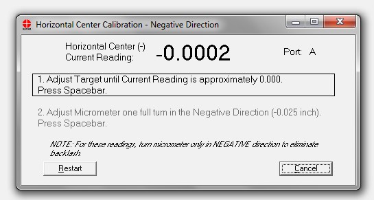
- Adjust the small micrometer until the reading is near zero. Press the space bar to record the reading.
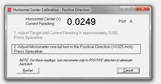
- Turn the micrometer 1 full turn in the positive direction. Press the spacebar to record the reading.
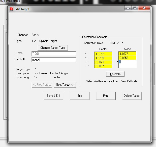
- Turn the micrometer back to the starting point and select H- Center. Click Calibrate.
- Press the spacebar to record the reading.
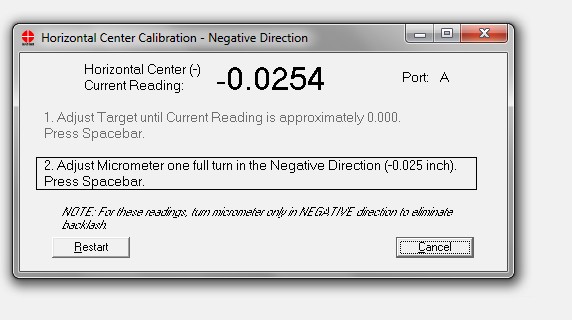
- Turn the micrometer 1 full turn in the negative direction. Press the spacebar to record the reading.
- Turn the micrometer back to the starting point and select H+ Slope. Click Calibrate.
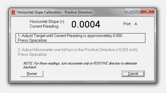
- Adjust the large micrometer until the reading is near zero. Press the spacebar to record the reading.
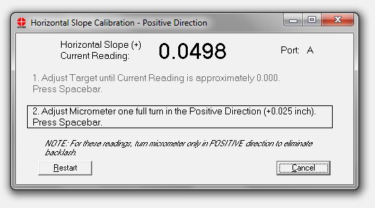
- Turn the micrometer 1 full turn in the positive direction. The reading should be near .050”. The target pivots on a 6” length so 1 full turn of the micrometer (.025”) will be .050”/Ft. Press the spacebar to record the readiing.
- Turn the micrometer back to the starting point and select V- Slope. Click Calibrate.
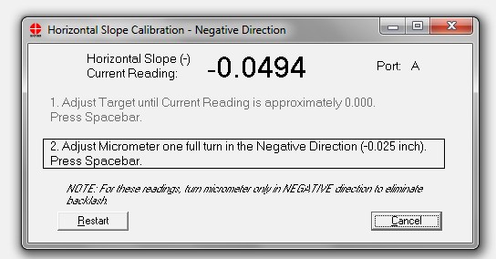
- Turn the micrometer 1 full turn in the negative direction. The reading should be near .050”. The target pivots on a 6” length so 1 full turn (.025”) will be .050”/Ft. Press the spacebar to record the reading.
- Click Save & Exit. If you only click Exit the data new calibration factors will not be saved..